Hirdetés
-

PROHARDVER!
Arduino hardverrel és szoftverrel foglakozó téma. Minden mikrovezérlő ami arduinoval programozható, és minden arduino program, board, és hardverrel kapcsolatos kérdések helye.

Új hozzászólás Aktív témák
-

olli
tag
Az ESP32 WEB SERVER működésével ismerkedem, kérdés:
a mobilon megadott IP címemmel megnyílt oldalon állítok egy csúszkát, a modul soros porton kiírja a számértékét. A router Wi-Fi kapcsolat ~ 20 méteres hatótávval bír, ennek duplájánról is működik a beállítás. Akkor a mobil neten keresztül és nem közvetlen a routerrel? -
-
-
olli
tag
disp.setI2CAddress(OLED_Address<<1);
disp.setFont(DEFAULTFONT);
startwritemS = millis();
delay(50);
endwritemS = millis();
timemS = endwritemS - startwritemS;
disp.setCursor(0, 3);
disp.print(message.charAt(3));
disp.print(message.charAt(4));
disp.print(message.charAt(5));
disp.print(message.charAt(6));
disp.print(message.charAt(7));
disp.print(F(" mS "));
disp.print(timemS);
disp.print(F(" mS"));
Az oleden a 3. sorban elöl felvillan 3-7char= HELLO, tartósan megjeleníti mS 49 mS.
A HELLO miért nem jelenik meg tartósan? -
olli
tag
válasz
 Sebiferi
#20674
üzenetére
Sebiferi
#20674
üzenetére
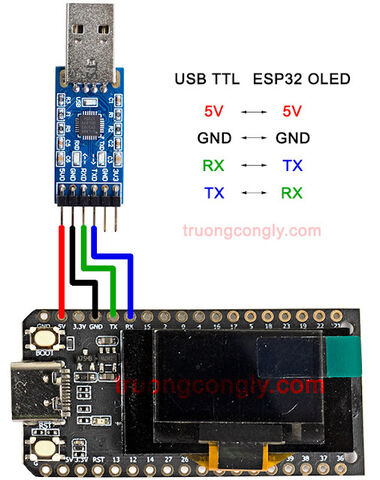
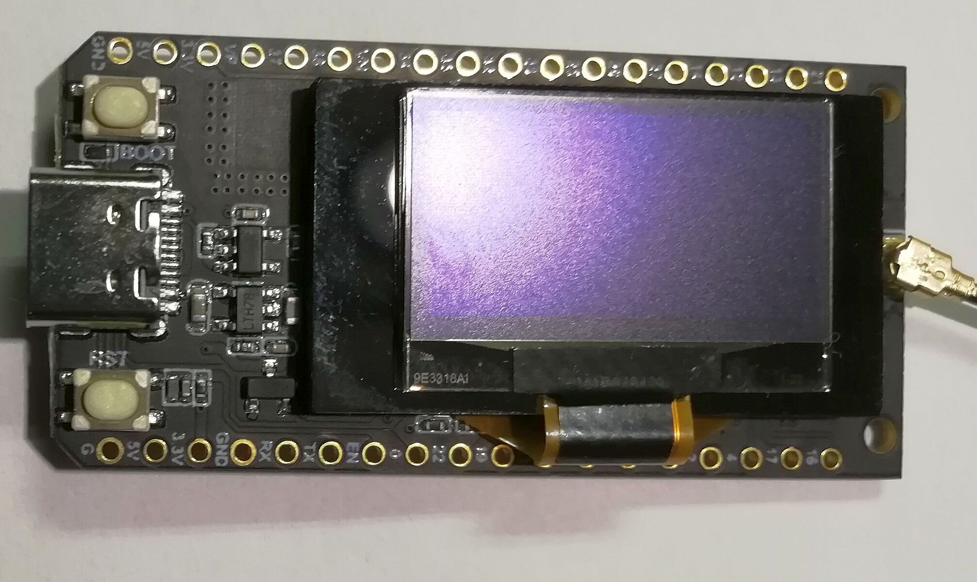
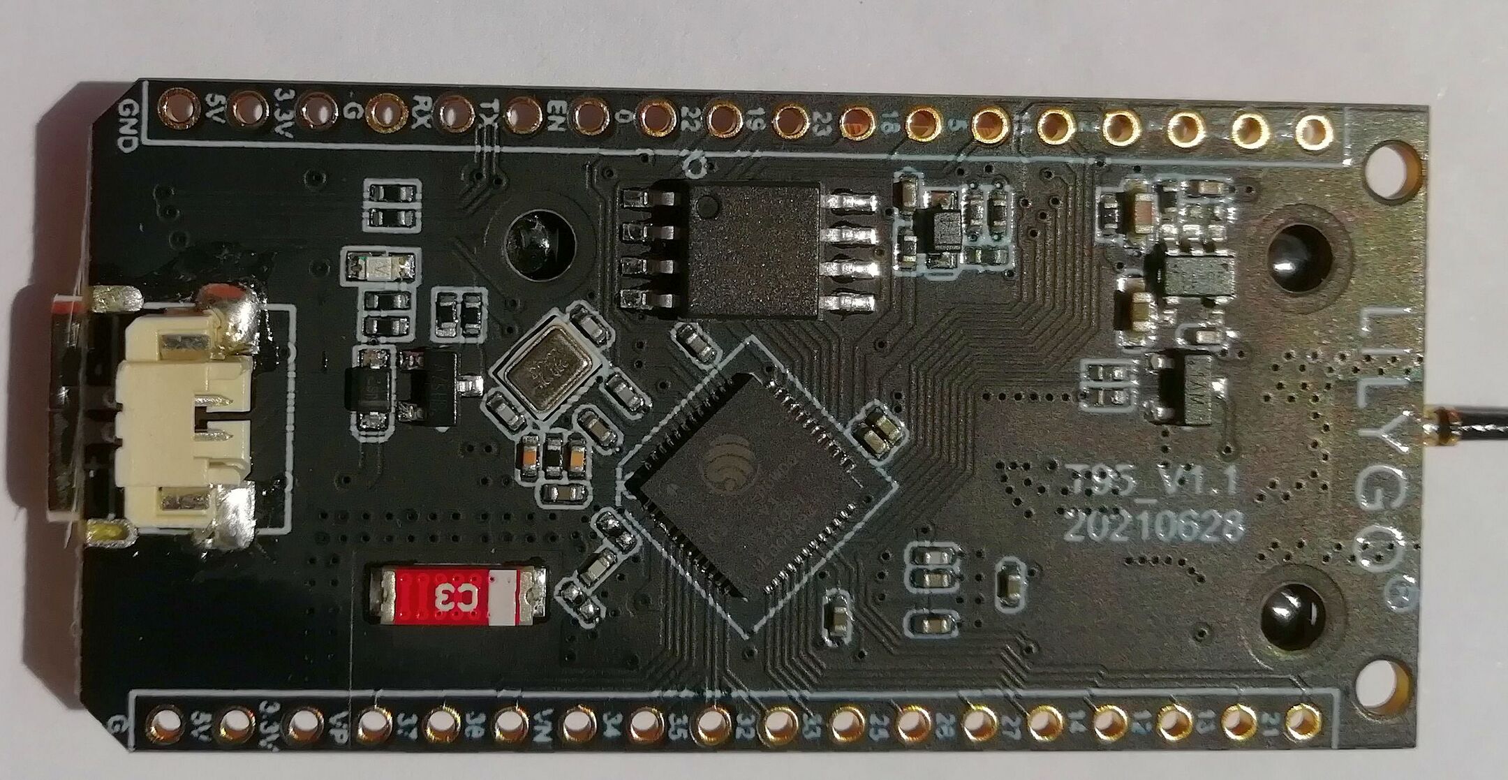
A kérdés az hogy hová tűnt el a lilygo. Kezdtem megismerkedni velük, közvetlenül rendeltem meg a LILYGO T-U2T-t, rendben, gyorsan leszállították, erre elérhetetlen a weblapjuk.
Az első feladat a lap érintkezőinek beazonosítása, jelenleg nem működik a LoRa protokol, wifi, oled igen, tehát érdekelne milyen érintkezőket mihez rendeltek a gyártók. A Heltec wifi_lora_oled más kiosztású.
Viszont levelezésben megadott linken meg elérhetőek. -
olli
tag
[link]
Lehet ez is egy újabb tévedés.
Viszont mindig tanul az ember, az össze-visszaságban egyszer csak sikerül rendet tenni, ráállni egy megbízható hw-sw vonalra.
Maga a modul rendben van, saját fejlesztgetéssel valószínűleg arra is alkalmas lesz amire eredetileg szántam. -
olli
tag
Megérkezett a LILYGO T-U2T, összecsatlakoztatás után az első példaprogram feltöltve: 31_SSD1306_SH1106_OLED_Checker.ino
Sketch uses 280069 bytes (21%) of program storage space. Maximum is 1310720 bytes.
Global variables use 22816 bytes (6%) of dynamic memory, leaving 304864 bytes for local variables. Maximum is 327680 bytes.
esptool.py v4.5.1
Serial port COM7
Connecting....
Chip is ESP32-D0WDQ6-V3 (revision v3.0)
Features: WiFi, BT, Dual Core, 240MHz, VRef calibration in efuse, Coding Scheme None
Crystal is 40MHz
MAC: 58:bf:25:05:64:20
Uploading stub...
Running stub...
Stub running...
Changing baud rate to 921600
Changed.
Configuring flash size...
Flash will be erased from 0x00001000 to 0x00005fff...
Flash will be erased from 0x00008000 to 0x00008fff...
Flash will be erased from 0x0000e000 to 0x0000ffff...
Flash will be erased from 0x00010000 to 0x00054fff...
Compressed 18960 bytes to 13073...
Writing at 0x00001000... (100 %)
Wrote 18960 bytes (13073 compressed) at 0x00001000 in 0.5 seconds (effective 327.8 kbit/s)...
Hash of data verified.
Compressed 3072 bytes to 146...
Writing at 0x00008000... (100 %)
Wrote 3072 bytes (146 compressed) at 0x00008000 in 0.1 seconds (effective 401.1 kbit/s)...
Hash of data verified.
Compressed 8192 bytes to 47...
Writing at 0x0000e000... (100 %)
Wrote 8192 bytes (47 compressed) at 0x0000e000 in 0.1 seconds (effective 608.7 kbit/s)...
Hash of data verified.
Compressed 280432 bytes to 156627...
Writing at 0x00010000... (10 %)
Writing at 0x0001c134... (20 %)
Writing at 0x00024a18... (30 %)
Writing at 0x00029e5e... (40 %)
Writing at 0x0002f382... (50 %)
Writing at 0x000348f6... (60 %)
Writing at 0x0003cfb8... (70 %)
Writing at 0x00046935... (80 %)
Writing at 0x0004bd9b... (90 %)
Writing at 0x00051491... (100 %)
Wrote 280432 bytes (156627 compressed) at 0x00010000 in 2.2 seconds (effective 1012.2 kbit/s)...
Hash of data verified.
Leaving...
Hard resetting via RTS pin... -
olli
tag
válasz
 Undoroid
#20623
üzenetére
Undoroid
#20623
üzenetére
esp32
c:\Users\win11\AppData\Local\Arduino15\packages\esp32\hardware\esp32\2.0.9\libraries\WiFi\
c:\Users\win11\AppData\Local\Arduino15\packages\esp32\hardware\esp32\2.0.9\libraries\SPI\
avr
c:\Users\win11\AppData\Local\Arduino15\packages\arduino\hardware\avr\1.8.6\libraries\SPI\
saját
c:\Arduino\libraries\
IDE2.1
c:\Program Files\Arduino IDE\
A saját telepítési útvonalaidat nézd át, ugyan az a könyvtár előfordulhat több helyen, ill. látni kell a meglevő könyvtárakat. -
olli
tag
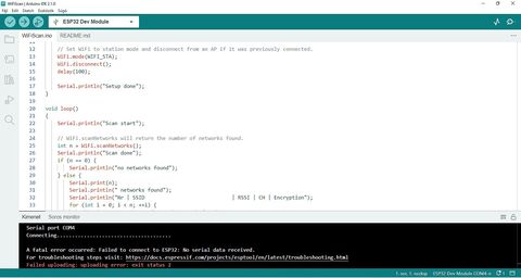
Boot folyamatosan nyomva, reset egyszer, boot felengedve a futó kijelzés leáll.
Továbbra is hiba a feltöltésnél.
A fatal error occurred: Failed to connect to ESP32: No serial data received.
For troubleshooting steps visit: https://docs.espressif.com/projects/esptool/en/latest/troubleshooting.html
Failed uploading: uploading error: exit status 2 -
olli
tag
válasz
 Wolfram
#20601
üzenetére
Wolfram
#20601
üzenetére
Táppal, hordozható lefedettség mérésre, kijelzéssel; wifinél nagyobb távolságokra smart rendszerhez.
A vasas locsolóvíz miatt zónánként eltérően szükség van egy hálózati vizes utánlocsolásra a ciklus befejezésekor, tehát sima villany le-fel kapcsolgatásnál összetettebb rendszerekhez. -
olli
tag
 FTDI232-vel com4 porton egyenlőre sikertelen a feltöltés.
Lehet helytelenül választottam lapot, vagy a feltöltéshez kell gombokat nyomogatni, vagy egyéb.
Ami még zavar:
Sketch uses 702225 bytes (53%) of program storage space. Maximum is 1310720 bytes.
Global variables use 42660 bytes (13%) of dynamic memory, leaving 285020 bytes for local variables. Maximum is 327680 bytes.
Mintha nem stimmelne terület mérete. -
-
olli
tag
-
-
-
olli
tag
válasz
Wolfram
#20534
üzenetére
In file included from c:\Arduino\libraries\WifiEspNow-main\src/WifiEspNowBroadcast.h:4:0,
from C:\Users\win11\AppData\Local\Temp\.arduinoIDE-unsaved2023430-7448-16to7q4.ddff\EspNowBroadcast\EspNowBroadcast.ino:15:
c:\Arduino\libraries\WifiEspNow-main\src/WifiEspNow.h:16:10: fatal error: cstddef: No such file or directory
#include <cstddef>
^~~~~~~~~
compilation terminated.
exit status 1
Compilation error: exit status 1LoRa32u4
Igen, ha minden passzol, de nem mindig.
[link] -
olli
tag
Lelkes amatőrként törekednem kell a megfelelő befektetés/haszon arányra.
Van egy hardwer gyártó, saját programozó platformmal, megtanulod, jön egy másik, meg újabbak. Standardok, szabványok, á minek.
Ezért kérdeztem a LoRa32u4 kapcsán más platformra.
Arduino alatt is sikerült a két esp közötti csomagküldésben a vezérlés megvalósítása, és ez volt a lényeg. -
olli
tag
válasz
Wolfram
#20525
üzenetére
ESP32-S2 WiFi+Bluetooth-compatible Internet Of Things Dual Type-C Development Board Core Board ESP32-S2-MINI-1 For Arduino5.09 Reviews56 SoldHUF 1,633.89HUF 1,993.4218% off
ESP32-C3 Development Board WiFi+Bluetooth 5.0 Equipped With ESP32-C3-MINI-1 ESP32 Wifi Internet Of Things Module For Arduino5.04 Reviews28 SoldHUF 1,160.45HUF 1,320.6412% off
Én meg ezeket az árakat találtam, de mindegy.
Már érdeklődtem a programozásukról, most az espressif esp-idf és az arduino ide közötti lehetőségeket néztem, nekem a parancs mód nem nagyon fekszik. -
olli
tag
válasz
 vargalex
#20469
üzenetére
vargalex
#20469
üzenetére
Kiíratás:
Received packet :1 HELLO 36.50 34.00 38369' with RSSI -99 Status: 1 BOILER
vagyis így már egy csomagból működik a pin 13 vezérlése is.
Korábban rákérdeztem az ESP-NOW vonalra a két esp közötti kommunikáció egyik protokolra. A jelen megoldás és az között stabilitás és kidolgozottság lenne csak a különbség? -
olli
tag
válasz
vargalex
#20460
üzenetére
"Received packet :1 HELLO 36.75 22.50 32342' with RSSI -82"
Jelenleg így íratom ki a csomagot, de csak az első karakterét, a state értékét is külön kellene megkapnom.
Szerinted hogyan nézzen ki a kód?#include <SPI.h>#include <LoRa.h>unsigned int state;//LoRa32u4 ports#define SS 8#define RST 4#define DI0 7#define BAND 433E6voidsetup() { Serial.begin(115200);pinMode(13, OUTPUT); // fehér led sets the pin as output for relaydigitalWrite(13,HIGH);//while (!Serial); //if just the the basic function, must connect to a computerdelay(1000);SPI.begin();LoRa.setPins(SS,RST,DI0);Serial.println("LoRa Receiver");if (!LoRa.begin(433E6)) {Serial.println("Starting LoRa failed!");while (1); }Serial.println("LoRa Initial OK!");}/*----( LOOP: RUNS CONSTANTLY )----*/void loop() {digitalWrite(13,LOW); // try to parse packetint packetSize = LoRa.parsePacket();if (packetSize) { // received a packetSerial.print("Received packet :"); // read packetwhile (LoRa.available()) {Serial.print((char)LoRa.read()); }// print RSSI of packetSerial.print("' with RSSI ");Serial.println(LoRa.packetRssi());}} -
olli
tag
válasz
 Janos250
#20453
üzenetére
Janos250
#20453
üzenetére
// try to parse packetint packetSizeMax = LoRa.parsePacket();if (packetSizeMax) {
uint8_t inChar[packetSizeMax] ;uint8_t i = 0 ;while (LoRa.available()) {inChar[i] = ((char)LoRa.read());Serial.print((char)inChar[i]);i++ ;Serial.print((char)LoRa.read());}}Így megfelel? -
olli
tag
loRa sender codban:
sensors.requestTemperatures();float T1 = sensors.getTempC(D0);float T2 = sensors.getTempC(D1);Serial.print("Sending packet: ");Serial.println(counter);// send packetLoRa.beginPacket();LoRa.print(state);LoRa.print(" ");LoRa.print("HELLO");LoRa.print(T1 );LoRa.print(" " );LoRa.print(T2 );LoRa.print(" ");LoRa.print(counter);LoRa.endPacket();counter++;ESP32u4 receiver codban:// try to parse packetint packetSize = LoRa.parsePacket();if (packetSize) {// received a packetSerial.print("Received packet :");// read packetwhile (LoRa.available()) {Serial.print((char)LoRa.read());}// print RSSI of packetSerial.print("' with RSSI ");Serial.println(LoRa.packetRssi());A packetből hogyan lehet a state értékét kinyerni? -
olli
tag
-
-
olli
tag
Mit kellene változtatni a kódban a state helyes funkcióhoz?
```cpp
#include <SPI.h>
#include <LoRa.h>
unsigned int state;
//LoRa32u4 ports
#define SS 8
#define RST 4
#define DI0 7
#define BAND 433E6
void setup() {
Serial.begin(115200);
pinMode(13, OUTPUT); // fehér led sets the pin as output for relay
digitalWrite(13,HIGH);
//while (!Serial); //if just the the basic function, must connect to a computer
delay(1000);
SPI.begin();
LoRa.setPins(SS,RST,DI0);
Serial.println("LoRa Receiver");
if (!LoRa.begin(433E6)) {
Serial.println("Starting LoRa failed!");
while (1);
}
Serial.println("LoRa Initial OK!");
}
/*----( LOOP: RUNS CONSTANTLY )----*/
void loop() {
digitalWrite(13,LOW);
// try to parse packet
int packetSize = LoRa.parsePacket();
if (packetSize) {
// received a packet
Serial.print("Received packet :");
// read packet
while (LoRa.available()) {
Serial.print((char)LoRa.read());
}
// print RSSI of packet
Serial.print("' with RSSI ");
Serial.println(LoRa.packetRssi());
if (state == 0) //Melegvíz gázkazánból..
{
Serial.println("GAZ_KAZAN - TIMER ON");
digitalWrite(13,LOW); //Időzítés be..
delay(500);
}
if (state == 1); //Melegvíz boilerből..
{
Serial.println("BOILER");
digitalWrite(13,HIGH); //Időzítő ki..
delay(3000);
}
}
}
//Serial print
// Received packet :1 HELLO 34.25 17.00 7056' with RSSI -79
//GAZ_KAZAN - TIMER ON
//BOILER
``` -
olli
tag
avrdude.exe: reading input file "0x00"
avrdude.exe: writing lfuse (1 bytes):
Writing | ################################################## | 100% 0.02s
avrdude.exe: 1 bytes of lfuse written
avrdude.exe: verifying lfuse memory against 0x00:
Reading | ################################################## | 100% 0.02s
Na ezt a részt nem értem.
Bepipáltam az írást, csak 0x00 beállítással fut le.
Nem írható felül, milyen filet kellene írni? -
olli
tag
válasz
 ekkold
#20236
üzenetére
ekkold
#20236
üzenetére
nano:
Sketch uses 2652 bytes (8%) of program storage space. Maximum is 30720 bytes.
Global variables use 462 bytes (22%) of dynamic memory, leaving 1586 bytes for local variables. Maximum is 2048 bytes.
uno:
Sketch uses 2652 bytes (8%) of program storage space. Maximum is 32256 bytes.
Global variables use 462 bytes (22%) of dynamic memory, leaving 1586 bytes for local variables. Maximum is 2048 bytes.
Több hely a program számára. -
-
olli
tag
```cpp
#define boiler 23 // villanyra kapcsol,rel1
#define gaz_kazan 17 // gázra kapcsol,rel2
#include <OneWire.h>
#include <DallasTemperature.h>
#define ONE_WIRE_BUS 13
OneWire oneWire(ONE_WIRE_BUS);
DallasTemperature sensors(&oneWire);
DeviceAddress D0 = { 0x28, 0x31, 0xBF, 0x29, 0x07, 0x00, 0x00, 0x7D }; // "T1"
DeviceAddress D1 = { 0x28, 0x4F, 0x8E, 0x2A, 0x07, 0x00, 0x00, 0x37 }; // "T2"
#include <Wire.h>
const char* ssid = "";
const char* password = "";
const char* ntpServer = "hu.pool.ntp.org";
const long gmtOffset_sec = 0;
const int daylightOffset_sec = 3600;
#define RTC_ADDRESS 0x68
#include <RtcDS3231.h>
RtcDS3231<TwoWire> Rtc(Wire);
// Convert normal decimal numbers to binary coded decimal
byte decToBcd(byte val){
return( (val/10*16) + (val%10) );
}
// Convert binary coded decimal to normal decimal numbers
byte bcdToDec(byte val){
return( (val/16*10) + (val%16) );
}
#include <Arduino.h>
#include "Wire.h"
#include "oled.h"
#include <WiFi.h>
#include "time.h"
#include <LoRa.h>
#define SCK 5 // GPIO5 -- SX1278's SCK
#define MISO 19 // GPIO19 -- SX1278's MISO
#define MOSI 27 // GPIO27 -- SX1278's MOSI
#define SS 18 // GPIO18 -- SX1278's CS
#define RST 14 // GPIO14 -- SX1278's RESET
#define DI0 26 // GPIO26 -- SX1278's IRQ(Interrupt Request)
#define BAND 433E6
unsigned int counter = 0;
String rssi = "RSSI --";
String packSize = "--";
String packet ;
struct tm timeinfo;
static char msg[20]; // character buffer
OLED display = OLED(4, 15, 16, 0x3C, 128, 32, true); // SSD1306
void szelep_vez ()
//T1+T2 >75 II T1>50= a boilerben van melegvíz
//rel2/pin17 villanyra kapcsol
//T1+T2<75 II T1<50= gáz melegíti a vizet
//rel1/pin23 gázra kapcsol
{
sensors.requestTemperatures();
float T1 = sensors.getTempC(D0);
float T2 = sensors.getTempC(D1);
if((T1+T2) > 75 || T1>49)
{
display.begin();
display.clear();
display.draw_string(4, 8, "BOILER", OLED::DOUBLE_SIZE);
display.display();
digitalWrite(boiler, HIGH);
digitalWrite(gaz_kazan, LOW);
delay(5000);
}
else
{
display.begin();
display.clear();
display.draw_string(4, 8, "GAZ_KAZAN", OLED::DOUBLE_SIZE);
display.display();
digitalWrite(gaz_kazan, HIGH);
digitalWrite(boiler, LOW);
delay(5000);
}
}
void setup(){
pinMode(boiler, OUTPUT); //villanyra kapcsol
digitalWrite(boiler, LOW);
pinMode(gaz_kazan, OUTPUT); //gázra kapcsol
digitalWrite(gaz_kazan, LOW);
pinMode(16,OUTPUT);
pinMode(25,OUTPUT);
digitalWrite(16, LOW); // set GPIO16 low to reset OLED
delay(50);
digitalWrite(16, HIGH); // while OLED is running, must set GPIO16 in high
Serial.begin(115200);
while (!Serial);
SPI.begin(SCK,MISO,MOSI,SS);
LoRa.setPins(SS,RST,DI0);
if (!LoRa.begin(433E6)) {
Serial.println("Starting LoRa failed!");
while (1);
}
Serial.println("init ok");
Wire.begin();
Serial.setDebugOutput(true);
//setTime(&timeinfo); // Valamikor be kell állítani az órát...
Serial.print("Connecting to ");
Serial.print(ssid);
WiFi.begin(ssid, password);
while (WiFi.status() != WL_CONNECTED) {
delay(500);
Serial.print(".");
}
Serial.println("");
Serial.println("WiFi connected.");
// Init and get the time
configTime(gmtOffset_sec, daylightOffset_sec, ntpServer);
printLocalTime();
Serial.println();
Serial.print("Connected! IP address: ");
Serial.println(WiFi.localIP());
//disconnect WiFi as it's no longer needed
WiFi.disconnect(true);
WiFi.mode(WIFI_OFF);
display.begin();
display.clear();
display.draw_string(4, 8, "RTC clock", OLED::DOUBLE_SIZE);
display.display();
//------- Initialize the Temperature measurement library--------------
sensors.begin();
sensors.setResolution(D0, 10); //T1
sensors.setResolution(D1, 10); //T2
// set the initial time here:
//DS3231 seconds, minutes, hours, day, date, month, year
//setDS3231time(00,34,12,2,6,3,23);
}
void loop(){
sensors.requestTemperatures();
float T1 = sensors.getTempC(D0);
float T2 = sensors.getTempC(D1);
Serial.print("Sending packet: ");
Serial.println(counter);
// send packet
LoRa.beginPacket();
LoRa.print("hello ");
LoRa.print( T1);
LoRa.print( T2 );
LoRa.print(counter);
LoRa.endPacket();
counter++;
digitalWrite(25, HIGH); // turn the LED on (HIGH is the voltage level)
delay(1000); // wait for a second
digitalWrite(25, LOW); // turn the LED off by making the voltage LOW
delay(1000);
getLocalTime(&timeinfo); // display time/date
Serial.println(&timeinfo, "%A, %B %d %Y %H:%M:%S");
RtcTemperature temp = Rtc.GetTemperature();
temp.Print(Serial);
// you may also get the temperature as a float and print it
// Serial.print(temp.AsFloatDegC());
Serial.println(" C ");
display.clear();
strftime (msg, 15, "%Y-%b-%d %a ", &timeinfo);
display.draw_string(16, 1, msg); // Display date
strftime (msg, 10, "%T ", &timeinfo); // Display time
display.draw_string(8, 12, msg, OLED::DOUBLE_SIZE);
display.display(); // Refresh screen
delay(3000);
display.clear();
display.setCursor(8,0);
display.println("T1= ");
display.setCursor(30,0);
display.println(T1);
display.setCursor(60, 0);
display.println(" C");
display.setCursor(8,12);
display.println("T2= ");
display.setCursor(30,12);
display.println(T2);
display.setCursor(60, 12);
display.println(" C");
display.display();
Serial.print(sensors.getTempC(D0));
Serial.println(" C");
Serial.print(sensors.getTempC(D1));
Serial.println(" C ");
//printLocalTime(); // display the real-time clock data on the Serial Monitor,
delay(1000); // every second
szelep_vez();
}
//--- Set RTC time/date ------------------------------------
void setLocalTime(struct tm* time) {
struct tm timeinfo;
Wire.beginTransmission(RTC_ADDRESS);
Wire.write(0); // set register pointer to 00h
Wire.write(decToBcd(time->tm_sec)); // set seconds
Wire.write(decToBcd(time->tm_min)); // set minutes
Wire.write(decToBcd(time->tm_hour)); // set hours
Wire.write(time->tm_wday + 1); // set day of week (1=Sun, 7=Sat)
Wire.write(decToBcd(time->tm_mday)); // set date (1 to 31)
Wire.write(decToBcd(time->tm_mon) + 1); // set month
Wire.write(decToBcd(time->tm_year - 100)); // year from 2000 (0 to 99)
Wire.endTransmission();
}
//--- Read time/date from RTC ------------------------------
void getTime(struct tm* time) {
Wire.beginTransmission(RTC_ADDRESS);
Wire.write(0); // a kiolvasás kezdőcímének beállítása
Wire.endTransmission(false);
Wire.requestFrom(RTC_ADDRESS, 7); // Hét bájt kiolvasása (time/date)
time->tm_sec = bcdToDec(Wire.read() & 0x7f); // Másodpercek (0-59)
time->tm_min = bcdToDec(Wire.read()); // Percek (0 - 59)
time->tm_hour = bcdToDec(Wire.read() & 0x3f); // Órák (24h kijelzéshez)
time->tm_wday = bcdToDec(Wire.read() - 1); // Hét napja (0 - 6)
time->tm_mday = bcdToDec(Wire.read()); // hónap napja (1 - 31)
time->tm_mon = bcdToDec(Wire.read() - 1); // hónap sorszáma (0 - 11)
time->tm_year = bcdToDec(Wire.read()) + 100; // 1900-tól eltelt évek
}
void printLocalTime(){
struct tm timeinfo;
if(!getLocalTime(&timeinfo)){
Serial.println("Failed to obtain time");
return;
}
Serial.println(&timeinfo, "%A, %B %d %Y %H:%M:%S");
Serial.print("Day of week: ");
Serial.println(&timeinfo, "%A");
Serial.print("Month: ");
Serial.println(&timeinfo, "%B");
Serial.print("Day of Month: ");
Serial.println(&timeinfo, "%d");
Serial.print("Year: ");
Serial.println(&timeinfo, "%Y");
Serial.print("Hour: ");
Serial.println(&timeinfo, "%H");
Serial.print("Hour (12 hour format): ");
Serial.println(&timeinfo, "%I");
Serial.print("Minute: ");
Serial.println(&timeinfo, "%M");
Serial.print("Second: ");
Serial.println(&timeinfo, "%S");
Serial.println("Time variables");
char timeHour[3];
strftime(timeHour,3, "%H", &timeinfo);
Serial.println(timeHour);
char timeWeekDay[10];
strftime(timeWeekDay,10, "%A", &timeinfo);
Serial.println(timeWeekDay);
Serial.println();
}
/*void setup_sntp() {
const char* ntpServer = "hu.pool.ntp.org"; // regionális NTP hálózat
const char* time_zone = "CET-1CEST,M3.5.0,M10.5.0/3"; // Europe/Budapest időzóna
configTzTime(time_zone, ntpServer); // Időzóna megadása
Serial.println("Connecting to sntp server");
while (!getLocalTime(&timeinfo)) {Serial.print(".");} // Pontosidő lekérése
setTime(&timeinfo); // A DS3231 RTC beállítása
Serial.println(" NTP connected");
Serial.println(&timeinfo, "NTP time: %A, %B %d %Y %H:%M:%S");
}*/
``` -
olli
tag
sensors.requestTemperatures();
float T1 = sensors.getTempC(D0);
float T2 = sensors.getTempC(D1);
Serial.print("Sending packet: ");
Serial.println(counter);
// send packet
LoRa.beginPacket();
LoRa.print("hello ");
LoRa.print( T1);
LoRa.print( T2 );
LoRa.print(counter);
LoRa.endPacket();
A küldő LoRa packet összeállítása jelenleg.
Még nem világos, így mitől =0 az állapot?
Továbbra is küldeném a fenti adatokat + a relé kapcsolását.
Egyszerre, vagy külön mehet? -
olli
tag
```cpp
#include <SPI.h>
#include <LoRa.h>
int state;
//LoRa32u4 ports
#define SS 8
#define RST 4
#define DI0 7
#define BAND 433E6
void setup() {
Serial.begin(115200);
pinMode(13, OUTPUT); // fehér led sets the pin as output for relay
digitalWrite(13,HIGH);
//while (!Serial); //if just the the basic function, must connect to a computer
delay(1000);
SPI.begin();
LoRa.setPins(SS,RST,DI0);
Serial.println("LoRa Receiver");
if (!LoRa.begin(433E6)) {
Serial.println("Starting LoRa failed!");
while (1);
}
Serial.println("LoRa Initial OK!");
}
/*----( LOOP: RUNS CONSTANTLY )----*/
void loop() {
digitalWrite(13,LOW);
// try to parse packet
int packetSize = LoRa.parsePacket();
if (packetSize) {
// received a packet
Serial.print("Received packet :");
// read packet
while (LoRa.available()) {
Serial.print((char)LoRa.read());
}
// print RSSI of packet
Serial.print("' with RSSI ");
Serial.println(LoRa.packetRssi());
while (LoRa.available()) {
Serial.println();
state = ((char)LoRa.read());
}
if (state == 1) //If this code received then turn on pump
{
Serial.println("Pump ON");
digitalWrite(13,LOW); //Pump relay ON
delay(500);
}
if (state == 0) //If this code received then turn off pump
{
Serial.println("Tank Full - Pump OFF");
digitalWrite(13,HIGH); //Pump relay OFF
delay(3000);
}
}
}serial print:```
Received packet :hello 16.2515.25112121' with RSSI -78 Tank Full - Pump OFFKüldő oldalon mit is kellene megadnom, hogy kiváltsa a relé on-off kapcsolását? -
olli
tag
válasz
 lanszelot
#19744
üzenetére
lanszelot
#19744
üzenetére
Ez az érzékelő nem egyedi alkohol vegyi érzékelő, nem gázkromatográf, nem ilyen egyedi mérőeszköz: [link]
[link]
If you power off the heater letting the temperature goes down, you have to preheat it again, every time.
We can detect more than one gas, but, keep in mind that it's not a true single gas detection. The chemical resistance inside this sensor react (if heated), to more than one gas, it can not isolate a single gas. So, what you get by conversion, is a resistance value to a ppm value, of many gas. However, if just one gas changed, or the other gases remains almost constant, you can get that changes. If you are able to mantain constant values for all the gas, and modify just one gas, then you can obtain the gas response over the sensor. The builder of this sensor does this job, making the figure i use for gas convertion. You can not be shure you are measuring just one gas.
Also consider that, the chimical resistance degradate in a few years, I've read somewhere (can't remember well), 2 years. -
olli
tag
[link] rtc_master
[link] oled könyvtár
[link] szintén,
ezek hiba nélkül fordítódnak esp32+ds3231 kódban.
Ami nem sikerül, az aktuális dátum/idő másnap, reset után, csak a fordítás időpontját mutatja.
25.50 C
20.25 C
32.00 C
Sending packet: 10
Saturday, March 04 2023 20:04:17
Mai állapot.
#include <OneWire.h>
#include <DallasTemperature.h>
#define ONE_WIRE_BUS 13
OneWire oneWire(ONE_WIRE_BUS);
DallasTemperature sensors(&oneWire);
DeviceAddress D0 = { 0x28, 0x31, 0xBF, 0x29, 0x07, 0x00, 0x00, 0x7D }; // "T1"
DeviceAddress D1 = { 0x28, 0x4F, 0x8E, 0x2A, 0x07, 0x00, 0x00, 0x37 }; // "T2"
/* for normal hardware wire use above */
#include <Wire.h>
#include <RtcDS3231.h>
RtcDS3231<TwoWire> Rtc(Wire);
// handy routine to return true if there was an error
// but it will also print out an error message with the given topic
bool wasError(const char* errorTopic = "")
{
uint8_t error = Rtc.LastError();
if (error != 0)
{
Serial.print("[");
Serial.print(errorTopic);
Serial.print("] WIRE communications error (");
Serial.print(error);
Serial.print(") : ");
switch (error)
{
case Rtc_Wire_Error_None:
Serial.println("(none?!)");
break;
case Rtc_Wire_Error_TxBufferOverflow:
Serial.println("transmit buffer overflow");
break;
case Rtc_Wire_Error_NoAddressableDevice:
Serial.println("no device responded");
break;
case Rtc_Wire_Error_UnsupportedRequest:
Serial.println("device doesn't support request");
break;
case Rtc_Wire_Error_Unspecific:
Serial.println("unspecified error");
break;
case Rtc_Wire_Error_CommunicationTimeout:
Serial.println("communications timed out");
break;
}
return true;
}
return false;
}
#include <Arduino.h>
#include "Wire.h"
#include "oled.h"
#include <WiFi.h>
#include "time.h"
#include <LoRa.h>
#include "secrets.h" // WiFi SSID & password
#define SCK 5 // GPIO5 -- SX1278's SCK
#define MISO 19 // GPIO19 -- SX1278's MISO
#define MOSI 27 // GPIO27 -- SX1278's MOSI
#define SS 18 // GPIO18 -- SX1278's CS
#define RST 14 // GPIO14 -- SX1278's RESET
#define DI0 26 // GPIO26 -- SX1278's IRQ(Interrupt Request)
#define BAND 433E6
unsigned int counter = 0;
#define RTC_ADDRESS 0x68 // I2C eszköz címe
String rssi = "RSSI --";
String packSize = "--";
String packet ;
struct tm timeinfo;
static char msg[20]; // character buffer
OLED display = OLED(4, 15, 16, 0x3C, 128, 32, true); // SSD1306
void setup() {
pinMode(16,OUTPUT);
pinMode(25,OUTPUT);
digitalWrite(16, LOW); // set GPIO16 low to reset OLED
delay(50);
digitalWrite(16, HIGH); // while OLED is running, must set GPIO16 in high
Serial.begin(115200);
while (!Serial);
SPI.begin(SCK,MISO,MOSI,SS);
LoRa.setPins(SS,RST,DI0);
if (!LoRa.begin(433E6)) {
Serial.println("Starting LoRa failed!");
while (1);
}
Serial.println("init ok");
Wire.begin();
display.begin();
display.clear();
display.draw_string(4, 8, "RTC clock", OLED::DOUBLE_SIZE);
display.display();
//------- Initialize the Temperature measurement library--------------
sensors.begin();
sensors.setResolution(D0, 10); //T1
sensors.setResolution(D1, 10); //T2
}
void loop() {
sensors.requestTemperatures();
float T1 = sensors.getTempC(D0);
float T2 = sensors.getTempC(D1);
Serial.print("Sending packet: ");
Serial.println(counter);
// send packet
LoRa.beginPacket();
LoRa.print("hello ");
LoRa.print(counter);
LoRa.endPacket();
counter++;
digitalWrite(25, HIGH); // turn the LED on (HIGH is the voltage level)
delay(1000); // wait for a second
digitalWrite(25, LOW); // turn the LED off by making the voltage LOW
delay(1000);
getTime(&timeinfo); // display time/date
Serial.println(&timeinfo, "%A, %B %d %Y %H:%M:%S");
RtcTemperature temp = Rtc.GetTemperature();
if (!wasError("loop GetTemperature"))
{
temp.Print(Serial);
// you may also get the temperature as a float and print it
// Serial.print(temp.AsFloatDegC());
Serial.println(" C ");
}
display.clear();
strftime (msg, 15, "%Y-%b-%d %a ", &timeinfo);
display.draw_string(16, 1, msg); // Display date
strftime (msg, 10, "%T ", &timeinfo); // Display time
display.draw_string(8, 12, msg, OLED::DOUBLE_SIZE);
display.display(); // Refresh screen
delay(3000);
display.clear();
display.setCursor(8,0);
display.println("T1= ");
display.setCursor(30,0);
display.println(T1);
display.setCursor(60, 0);
display.println(" C");
display.setCursor(8,12);
display.println("T2= ");
display.setCursor(30,12);
display.println(T2);
display.setCursor(60, 12);
display.println(" C");
display.display();
Serial.print(sensors.getTempC(D0));
Serial.println(" C");
Serial.print(sensors.getTempC(D1));
Serial.println(" C ");
}
//--- Convert decimal numbers to BCD -----------------------
byte decToBcd(byte val) {
return ( (val / 10 * 16) + (val % 10) );
}
//--- Convert BCD numbers to decimal ----------------------
byte bcdToDec(byte val) {
return ( (val / 16 * 10) + (val % 16) );
}
/*--- Set RTC time/date ------------------------------------
void setTime(struct tm* time) {
Wire.beginTransmission(RTC_ADDRESS);
Wire.write(0); // set register pointer to 00h
Wire.write(decToBcd(time->tm_sec)); // set seconds
Wire.write(decToBcd(time->tm_min)); // set minutes
Wire.write(decToBcd(time->tm_hour)); // set hours
Wire.write(time->tm_wday + 1); // set day of week (1=Sun, 7=Sat)
Wire.write(decToBcd(time->tm_mday)); // set date (1 to 31)
Wire.write(decToBcd(time->tm_mon) + 1); // set month
Wire.write(decToBcd(time->tm_year - 100)); // year from 2000 (0 to 99)
Wire.endTransmission();
}*/
//--- Read time/date from RTC ------------------------------
void getTime(struct tm* time) {
Wire.beginTransmission(RTC_ADDRESS);
Wire.write(0); // a kiolvasás kezdőcímének beállítása
Wire.endTransmission(false);
Wire.requestFrom(RTC_ADDRESS, 7); // Hét bájt kiolvasása (time/date)
time->tm_sec = bcdToDec(Wire.read() & 0x7f); // Másodpercek (0-59)
time->tm_min = bcdToDec(Wire.read()); // Percek (0 - 59)
time->tm_hour = bcdToDec(Wire.read() & 0x3f); // Órák (24h kijelzéshez)
time->tm_wday = bcdToDec(Wire.read() - 1); // Hét napja (0 - 6)
time->tm_mday = bcdToDec(Wire.read()); // hónap napja (1 - 31)
time->tm_mon = bcdToDec(Wire.read() - 1); // hónap sorszáma (0 - 11)
time->tm_year = bcdToDec(Wire.read()) + 100; // 1900-tól eltelt évek
} -
olli
tag
 A tényleges működés tesztelése következik a 230V mérőhely kialakítása után.
Közben elkezdhetek azon gondolkodni, hogy hogyan tovább egy napelemes rendszer vezérlés kivitelezéséhez.
Mérve a kétirányú energiát, kitáplálás helyett optimalizálni kell a ház fogyasztását, esetleg tárolni átmeneti pufferben. -
olli
tag
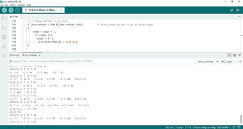
Visszaírtam az eredeti gomb értékeket.
Sd-re és serialra kiírja a mérések eredményét, a kijelző csak villog.
A SELECT-et 1024-600 értékre módosítva a page=1 kiírja a megfelelő adatokat, de a page=2 és page=3 nem jeleníti meg.
A többi gomb lenyomása kivált lépést, 600-800 tartományban a SELECT nem. -
olli
tag
Right=285, Up=508, Down=735, Left=909, Select=983;
```cpp
//Right button is pressed
if (buttonRead <400)
```
```cpp
// Up button is pressed
if (buttonRead <600 && buttonRead > 400)
```
és így tovább, érzékeli, kivéve induláskor a select-et, az akkor nincs lenyomva az a gomb, valahol 400 és 600 közötti értéket mutat az A0.
Magasabb feszültséggel lehetne növelni, az egy átkapcsolás 10V-ról 5V-ra.
A gombok lenyomása után ~ nullázódnak az értékek mivel nincs még mérhető feszültség beadva a szenzorokra. -
olli
tag
 A szenzorok bekötve, mérés még nincs, egy ellenállás létra szolgál öt nyomógombbal a keypad funkciókkal.
Nem fut a gombok megnyomása utáni lcd kiírás, a frekvencia mérés után az első page == 1 kiírást jeleníti meg, visszalép a frekvencia mérésre és újra page == 1-re.
Hibás a kód, vagy ténylegesen végezzen mérést valós feszültséggel? -
olli
tag
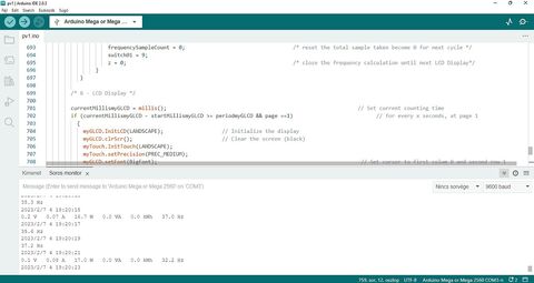
Köszi, működik.
A következő lépés az áram és feszmérő szenzorok csatlakoztatása.
Jelenleg a glcd-re kiírja az adatokat, printeli serialra.
Sd kártyára is megírtam csv-be mentésre, együtt a printseriallal
hibázik.
Csökkenteni kellene a glcd-re kiírás, a serialprint, sd mentés számát, vagy elhagyni valamelyiket? -
olli
tag
Sziasztok!
Energia mérőhöz az eredeti programban nyomógombos lcd szerepel, a gombokkal kalibrál. Az lcd az A0 lábon csatlakozik./* 0.1- Button Function */
int buttonRead;
buttonRead = analogRead (0); // Read analog pin A0. Pin A0 automatically assigned for LCD Display Button function (cannot be changed)
currentButtonMillis = millis();
if(currentButtonMillis - startButtonMillis >= 300)
{
//Right button is pressed
if (buttonRead < 60)
{
myGLCD.clrScr(); // Clear the screen (black)
myGLCD.setFont(BigFont);
myGLCD.setColor(0, 0, 255);
myGLCD.setBackColor(0, 0, 255);
myGLCD.print ("PRESS <SELECT> ",20,20);
myGLCD.print ("TO CALLIBRATE ",20,50);
}
// Up button is pressed
if (buttonRead < 200 && buttonRead > 60) // Press up button to go to upper page
{
page = page - 1 ;
if( page <=0)
{ page = 1;}
startButtonMillis = millis();
}
// Down button is pressed
if (buttonRead < 400 && buttonRead > 200) // Press down button to go to lower page
{
page = page + 1;
if (page >3)
{ page = 3;
}
startButtonMillis = millis();
}
// Left button is pressed
if (buttonRead < 600 && buttonRead >400)
{
myGLCD.clrScr(); // Clear the screen (black)
myGLCD.setFont(BigFont);
myGLCD.setColor(0, 0, 255);
myGLCD.setBackColor(0, 0, 255);
myGLCD.print ("PRESS <SELECT> ",20,20);
myGLCD.print ("TO CALLIBRATE ",20,50);
}
// Select button is pressed
if (buttonRead < 800 && buttonRead > 600)
{
currentOffsetRead = 1; // to activate offset for current
voltageOffsetRead = 1; // to activate offset for voltage
powerOffsetRead = 1; // to activate offset for power // set display words starting at upper left corner
myGLCD.print ("INITIALIZING..... ",20,120); // set display words starting at lower left corner
myGLCD.print ("WAIT 5 SEC ..... ",20,150);
}
}
A nyomógombos lcd hiányában kihagyható: // Offset will automatically callibrate when SELECT Button on the LCD Display Shield is pressed.
// If you do not have LCD Display Shield, look into serial monitor to add or minus the value manually and key in here.
Pontosan hogyan tudom módosítani az értéket?
Érintő képernyő + mega 2560 lesz az alap hardwer, az érintőképernyő
gombjaival ki lehet váltani a fizikai gombokat?
Pl. megoldás egy pwm lábon kiadni a feszültség szinteket az A0 lábra? -
olli
tag
Hi!
C:\Users\win11\OneDrive\Dokumentumok\Arduino\libraries\Bi-directional_AC_Energy_Meter\Bi-directional_AC_Energy_Meter.ino: In function 'void loop()':
C:\Users\win11\OneDrive\Dokumentumok\Arduino\libraries\Bi-directional_AC_Energy_Meter\Bi-directional_AC_Energy_Meter.ino:550:58: error: no matching function for call to 'UTFT::print(float&, int&)'
myGLCD.print(RMSVoltageMean,decimalPrecision );
^
In file included from C:\Users\win11\OneDrive\Dokumentumok\Arduino\libraries\Bi-directional_AC_Energy_Meter\Bi-directional_AC_Energy_Meter.ino:135:0:
c:\Users\win11\OneDrive\Dokumentumok\Arduino\libraries\UTFT/UTFT.h:215:8: note: candidate: void UTFT::print(char*, int, int, int)
void print(char *st, int x, int y, int deg=0);
^~~~~
c:\Users\win11\OneDrive\Dokumentumok\Arduino\libraries\UTFT/UTFT.h:215:8: note: candidate expects 4 arguments, 2 provided
c:\Users\win11\OneDrive\Dokumentumok\Arduino\libraries\UTFT/UTFT.h:216:8: note: candidate: void UTFT::print(String, int, int, int)
void print(String st, int x, int y, int deg=0);
^~~~~
c:\Users\win11\OneDrive\Dokumentumok\Arduino\libraries\UTFT/UTFT.h:216:8: note: candidate expects 4 arguments, 2 provided
exit status 1
Compilation error: no matching function for call to 'UTFT::print(float&, int&)'
A fenti hiba megoldására milyen módszert alkalmaznátok? -
olli
tag
Az Arduino IDE 1.8.7 verziót egyedül feltelepítve a DUE lappal futnak a beépített példák?
Ha az megy, az innen-onnan leszedettek meg nem, nyilván rossz a forrás, a hibaüzenetek segíthetnek.
Most megnéztem DUE-re egy saját programot, dobott egy csomó hibát, de tudom, hogy Mega-hoz vannak könyvtárak telepítve, azokat kellene törölni. -
olli
tag
[CODE// URTouch_ButtonTest
// Copyright (C)2015 Rinky-Dink Electronics, Henning Karlsen. All right reserved
// web: http://www.RinkyDinkElectronics.com/
//
// This program is a quick demo of how create and use buttons.
//
// This program requires the UTFT library.
//
// It is assumed that the display module is connected to an
// appropriate shield or that you know how to change the pin
// numbers in the setup.
//#include <UTFT.h>
#include <URTouch.h>// Initialize display
// ------------------
// Set the pins to the correct ones for your development board
// -----------------------------------------------------------
// Standard Arduino Uno/2009 Shield : <display model>,19,18,17,16
// Standard Arduino Mega/Due shield : <display model>,38,39,40,41
// CTE TFT LCD/SD Shield for Arduino Due : <display model>,25,26,27,28
// Teensy 3.x TFT Test Board : <display model>,23,22, 3, 4
// ElecHouse TFT LCD/SD Shield for Arduino Due : <display model>,22,23,31,33
//
// Remember to change the model parameter to suit your display module!
UTFT myGLCD(CTE32,25,26,27,28);// Initialize touchscreen
// ----------------------
// Set the pins to the correct ones for your development board
// -----------------------------------------------------------
// Standard Arduino Uno/2009 Shield : 15,10,14, 9, 8
// Standard Arduino Mega/Due shield : 6, 5, 4, 3, 2
// CTE TFT LCD/SD Shield for Arduino Due : 6, 5, 32, 3, 2
// Teensy 3.x TFT Test Board : 26,31,27,28,29
// ElecHouse TFT LCD/SD Shield for Arduino Due : 25,26,27,29,30
//
URTouch myTouch( 6, 5, 32, 3, 2);// Declare which fonts we will be using
extern uint8_t BigFont[];int x, y;
char stCurrent[20]="";
int stCurrentLen=0;
char stLast[20]="";/*************************
** Custom functions **
*************************/void drawButtons()
{
// Draw the upper row of buttons
for (x=0; x<5; x++)
{
myGLCD.setColor(0, 0, 255);
myGLCD.fillRoundRect (10+(x*60), 10, 60+(x*60), 60);
myGLCD.setColor(255, 255, 255);
myGLCD.drawRoundRect (10+(x*60), 10, 60+(x*60), 60);
myGLCD.printNumI(x+1, 27+(x*60), 27);
}
// Draw the center row of buttons
for (x=0; x<5; x++)
{
myGLCD.setColor(0, 0, 255);
myGLCD.fillRoundRect (10+(x*60), 70, 60+(x*60), 120);
myGLCD.setColor(255, 255, 255);
myGLCD.drawRoundRect (10+(x*60), 70, 60+(x*60), 120);
if (x<4)
myGLCD.printNumI(x+6, 27+(x*60), 87);
}
myGLCD.print("0", 267, 87);
// Draw the lower row of buttons
myGLCD.setColor(0, 0, 255);
myGLCD.fillRoundRect (10, 130, 150, 180);
myGLCD.setColor(255, 255, 255);
myGLCD.drawRoundRect (10, 130, 150, 180);
myGLCD.print("Clear", 40, 147);
myGLCD.setColor(0, 0, 255);
myGLCD.fillRoundRect (160, 130, 300, 180);
myGLCD.setColor(255, 255, 255);
myGLCD.drawRoundRect (160, 130, 300, 180);
myGLCD.print("Enter", 190, 147);
myGLCD.setBackColor (0, 0, 0);
}void updateStr(int val)
{
if (stCurrentLen<20)
{
stCurrent[stCurrentLen]=val;
stCurrent[stCurrentLen+1]='\0';
stCurrentLen++;
myGLCD.setColor(0, 255, 0);
myGLCD.print(stCurrent, LEFT, 224);
}
else
{
myGLCD.setColor(255, 0, 0);
myGLCD.print("BUFFER FULL!", CENTER, 192);
delay(500);
myGLCD.print(" ", CENTER, 192);
delay(500);
myGLCD.print("BUFFER FULL!", CENTER, 192);
delay(500);
myGLCD.print(" ", CENTER, 192);
myGLCD.setColor(0, 255, 0);
}
}// Draw a red frame while a button is touched
void waitForIt(int x1, int y1, int x2, int y2)
{
myGLCD.setColor(255, 0, 0);
myGLCD.drawRoundRect (x1, y1, x2, y2);
while (myTouch.dataAvailable())
myTouch.read();
myGLCD.setColor(255, 255, 255);
myGLCD.drawRoundRect (x1, y1, x2, y2);
}/*************************
** Required functions **
*************************/void setup()
{
// Initial setup
myGLCD.InitLCD();
myGLCD.clrScr();myTouch.InitTouch();
myTouch.setPrecision(PREC_MEDIUM);myGLCD.setFont(BigFont);
myGLCD.setBackColor(0, 0, 255);
drawButtons();
}void loop()
{
while (true)
{
if (myTouch.dataAvailable())
{
myTouch.read();
x=myTouch.getX();
y=myTouch.getY();if ((y>=10) && (y<=60)) // Upper row
{
if ((x>=10) && (x<=60)) // Button: 1
{
waitForIt(10, 10, 60, 60);
updateStr('1');
}
if ((x>=70) && (x<=120)) // Button: 2
{
waitForIt(70, 10, 120, 60);
updateStr('2');
}
if ((x>=130) && (x<=180)) // Button: 3
{
waitForIt(130, 10, 180, 60);
updateStr('3');
}
if ((x>=190) && (x<=240)) // Button: 4
{
waitForIt(190, 10, 240, 60);
updateStr('4');
}
if ((x>=250) && (x<=300)) // Button: 5
{
waitForIt(250, 10, 300, 60);
updateStr('5');
}
}if ((y>=70) && (y<=120)) // Center row
{
if ((x>=10) && (x<=60)) // Button: 6
{
waitForIt(10, 70, 60, 120);
updateStr('6');
}
if ((x>=70) && (x<=120)) // Button: 7
{
waitForIt(70, 70, 120, 120);
updateStr('7');
}
if ((x>=130) && (x<=180)) // Button: 8
{
waitForIt(130, 70, 180, 120);
updateStr('8');
}
if ((x>=190) && (x<=240)) // Button: 9
{
waitForIt(190, 70, 240, 120);
updateStr('9');
}
if ((x>=250) && (x<=300)) // Button: 0
{
waitForIt(250, 70, 300, 120);
updateStr('0');
}
}if ((y>=130) && (y<=180)) // Upper row
{
if ((x>=10) && (x<=150)) // Button: Clear
{
waitForIt(10, 130, 150, 180);
stCurrent[0]='\0';
stCurrentLen=0;
myGLCD.setColor(0, 0, 0);
myGLCD.fillRect(0, 224, 319, 239);
}
if ((x>=160) && (x<=300)) // Button: Enter
{
waitForIt(160, 130, 300, 180);
if (stCurrentLen>0)
{
for (x=0; x<stCurrentLen+1; x++)
{
stLast[x]=stCurrent[x];
}
stCurrent[0]='\0';
stCurrentLen=0;
myGLCD.setColor(0, 0, 0);
myGLCD.fillRect(0, 208, 319, 239);
myGLCD.setColor(0, 255, 0);
myGLCD.print(stLast, LEFT, 208);
}
else
{
myGLCD.setColor(255, 0, 0);
myGLCD.print("BUFFER EMPTY", CENTER, 192);
delay(500);
myGLCD.print(" ", CENTER, 192);
delay(500);
myGLCD.print("BUFFER EMPTY", CENTER, 192);
delay(500);
myGLCD.print(" ", CENTER, 192);
myGLCD.setColor(0, 255, 0);
}
}
}
}
}
}
]URTouch.h
/*
URTouch.h - Arduino/chipKit library support for Color TFT LCD Touch screens
Copyright (C)2016 Rinky-Dink Electronics, Henning Karlsen. All right reservedBasic functionality of this library are based on the demo-code provided by
ITead studio.You can find the latest version of the library at
http://www.RinkyDinkElectronics.com/This library is free software; you can redistribute it and/or
modify it under the terms of the CC BY-NC-SA 3.0 license.
Please see the included documents for further information.Commercial use of this library requires you to buy a license that
will allow commercial use. This includes using the library,
modified or not, as a tool to sell products.The license applies to all part of the library including the
examples and tools supplied with the library.
*/#ifndef URTouch_h
#define URTouch_h#define URTOUCH_VERSION 201
#if defined(__AVR__)
#include "Arduino.h"
#include "hardware/avr/HW_AVR_defines.h"
#elif defined(__PIC32MX__)
#include "WProgram.h"
#include "hardware/pic32/HW_PIC32_defines.h"
#elif defined(__arm__)
#include "Arduino.h"
#include "hardware/arm/HW_ARM_defines.h"
#endif#define PORTRAIT 0
#define LANDSCAPE 1#define PREC_LOW 1
#define PREC_MEDIUM 2
#define PREC_HI 3
#define PREC_EXTREME 4class URTouch
{
public:
int16_t TP_X ,TP_Y;URTouch(byte tclk, byte tcs, byte tdin, byte dout, byte irq);
void InitTouch(byte orientation = LANDSCAPE);
void read();
bool dataAvailable();
int16_t getX();
int16_t getY();
void setPrecision(byte precision);void calibrateRead();
private:
regtype *P_CLK, *P_CS, *P_DIN, *P_DOUT, *P_IRQ;
regsize B_CLK, B_CS, B_DIN, B_DOUT, B_IRQ;
byte T_CLK, T_CS, T_DIN, T_DOUT, T_IRQ;
long _default_orientation;
byte orient;
byte prec;
byte display_model;
long disp_x_size, disp_y_size, default_orientation;
long touch_x_left, touch_x_right, touch_y_top, touch_y_bottom;void touch_WriteData(byte data);
word touch_ReadData();#if defined(ENERGIA)
volatile uint32_t* portOutputRegister(int value);
volatile uint32_t* portInputRegister(int value);
#endif
};#endif
-
olli
tag
// Standard Arduino Mega/Due shield : <display model>,38,39,40,41
UTFT myGLCD(SSD1963_800480,38,39,40,41); //(byte model, int RS, int WR, int CS, int RST, int SER)UTouch myTouch( 43, 42, 44, 45, 46); //byte tclk, byte tcs, byte din, byte dout, byte irq
Ezekkel a beállításokkal?
A DUE-nak saját
#include <UTFT.h>
#include <URTouch.h>
könyvtára van. -
olli
tag
Nem a vezetékekben kialakuló áramlökésekre, a rádiófrekvenciás zavarra érzékeny, vagy sima program hibára, vagy ..... bármire lefagyhat.
Fűtés vezérlőt működtet egy nano lap, SSR relére cseréltem néhány power relét, csökkent a lefagyás, de:
jelenleg a vezérlés nem fut, csak hőfok mérés szenzorokkal, RTC, LCD, igaz van aktív nagyfeszültségű környezet és néha így is lefagy.
Más összeállításban az I2C LCD fagyogatott.


![;]](http://cdn.rios.hu/dl/s/v1.gif)


 IUAAOSwNRdX3gas
Új hozzászólás Aktív témák

- Samsung Galaxy S25 FE, 8/128, tengerészkék
- ZBook Power 15 G10 15.6" QHD IPS Ryzen 9 PRO 7940HS Radeon 780M 32GB 512GB NVMe ujjlolv IR kam gar
- Garmin Epix Pro Sapphire (51mm)
- Zalman WATTTERA ZM800-EBTII 800W táp - GARIS!
- Dell Precision 7530,15.6",FHD,Xeon E-2186M,32GB DDR4,256GB SSD,P2000 4GB VGA,WIN11
- Bomba ár! HP EliteBook 820 G2 - i5-5GEN I 8GB I 256GB SSD I 12,5" FHD I Cam I W10 I Garancia!
- Autós kamera eladó
- Újszerű HP 14s-dq5001nh - 14"FHD IPS - i5-1235U - 16GB - 512GB - Win11 - Magyar - Garancia
- Telefon felváráslás!! Samsung Galaxy S22/Samsung Galaxy S22+/Samsung Galaxy S22 Ultra
- Bontatlan iPhone 16 Pro (128 GB) (rendelhető)
Állásajánlatok

Cég: PCMENTOR SZERVIZ KFT.
Város: Budapest

Cég: ATW Internet Kft.
Város: Budapest