- Karácsonyfaként világíthat a Thermaltake új CPU-hűtője
- Az USA vizsgálja a RISC-V kínai terjedésének kockázatát
- Kicsit extrémre sikerült a Hyte belépője a készre szerelt vízhűtések világába
- Egészen nagy teljesítményspektrumon fedné le a mobil piacot az AMD
- Kihívás a középkategóriában: teszten a Radeon RX 7600 XT
- AMD K6-III, és minden ami RETRO - Oldschool tuning
- NVIDIA GeForce RTX 4080 /4080S / 4090 (AD103 / 102)
- Milyen cserélhető objektíves gépet?
- 3D nyomtatás
- Melyik tápegységet vegyem?
- Audiokultúra - Hi-Fi-ről hifisen
- Vezetékes FEJhallgatók
- Androidos tablet topic
- Milyen notebookot vegyek?
- Házimozi, és Hifi kábelezés!
Hirdetés
-


Új Beats fej- és fülhallgatók jelentek meg
ma Frissítette a Solo termékcsaládot az Apple házi audiomárkája.
-
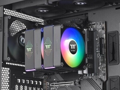

Karácsonyfaként világíthat a Thermaltake új CPU-hűtője
ph Az ASTRIA 600 ARGB ráadásul a hűtési teljesítmény szempontjából sem szégyenkezhet.
-
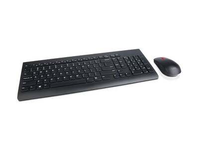

Lenovo Essential Wireless Combo
lo Lehet-e egy billentyűzet karcsú, elegáns és különleges? A Lenovo bebizonyította, hogy igen, de bosszantó is :)


-

PROHARDVER!
OLVASD VÉGIG ALAPOSAN MIELŐTT ÚJ HOZZÁSZÓLÁST ÍRNÁL!!!

Új hozzászólás Aktív témák
-

P.H.
senior tag
válasz
 Raymond
#2752
üzenetére
Raymond
#2752
üzenetére
Eddig jutottam pár nap alatt, tovább nem látom az utat, ezen leírás alapján*:
- K8 esetén ezt az egy FIFO-buffer-t találtam (NB -> HT?) :
3.6.18 HyperTransport™ FIFO Read Pointer Optimization Register
This register allows the separation of read/write pointers in the HyperTransport technology receive/transmit FIFOs to be changed from their default settings. The pointer separation written to this register takes effect after a warm reset. The value of this register is maintained through a warm reset and is initialized to 0 on a cold reset.Change Read Pointer For HyperTransport Link 2 Receiver (RcvRdPtrLdt2)—Bits 18–16.
Moves the read pointer for the HyperTransport receive FIFO closer to the write pointer thereby reducing latency through the receiver.
000b = RdPtr assigned by hardware
001b = Move RdPtr closer to WrPtr by 1 HyperTransport clock period
010b = Move RdPtr closer to WrPtr by 2 HyperTransport clock periods
011b = Move RdPtr closer to WrPtr by 3 HyperTransport clock periods
100b = Move RdPtr closer to WrPtr by 4 HyperTransport clock periods
101b = Move RdPtr closer to WrPtr by 5 HyperTransport clock periods
110b = Move RdPtr closer to WrPtr by 6 HyperTransport clock periods
111b = Move RdPtr closer to WrPtr by 7 HyperTransport clock periods
AMD recommends setting this field to 5 for all coherent HyperTransport links and noncoherent HyperTransport links to AMD chipsets. Optimal value for noncoherent
HyperTransport links to other chipsets needs to be determined by the developer and tested to ensure stability.Change Read Pointer For HyperTransport Link 2 Transmitter (XmtRdPtrLdt2)—Bits 21–20.
Moves the read pointer for the HyperTransport technology transmit FIFO closer to the write pointer thereby reducing latency through the transmitter.
00b = RdPtr assigned by hardware
01b = Move RdPtr closer to WrPtr by 1 HyperTransport clock period
10b = Move RdPtr closer to WrPtr by 2 HyperTransport clock periods
11b = Move RdPtr closer to WrPtr by 3 HyperTransport clock periods
AMD recommends setting this field to 2 for all coherent HyperTransport links and noncoherent HyperTransport links to AMD chipsets. Optimal value for noncoherent
HyperTransport links to other chipsets needs to be determined by the developer and tested to ensure stability.- az AMD által kiadott NPT Guide-ot kihagytam.
- K10 esetén viszont van több is:
[1]. F2x[1, 0]78 DRAM Control Register (169. oldal, NB -> MCT vagy NC -> DCTs?)
RdPtrInit: read pointer initial value. Read-write. There is a synchronization FIFO between the NB clock domain and memory clock domain. Each increment of this field positions the read pointer one half clock cycle closer to the write pointer thereby reducing the latency through the FIFO. This field should be written prior to DRAM initialization. It is recommended that these bits remain in the default state.
Bits Read to Write Pointer Separation
0000b - 0010b Reserved
0011b 2.5 MEMCLKs (For DDR3, this encoding is reserved.)
0100b 2 MEMCLKs
0101b 1.5 MEMCLKs
0110b Reserved
0111b - 1111b Reserved[2].F3xDC Clock Power/Timing Control 2 Register (242. oldal, NB -> core(s)?)
[bit 14:12] NbsynPtrAdj: NB/core synchronization FIFO pointer adjust. Read-write. Cold reset: 000b. There is a synchronization FIFO between the NB clock domain and CPU core clock domains. At cold reset, the read pointer and write pointer for each of these FIFOs is positioned conservatively, such that FIFO latency may be greater than is necessary. This field may be used to position the read pointer and write pointer of each FIFO closer to each other such that latency is reduced. Each increment of this field
represents one clock cycle of whichever is the slower clock (longer period) between the NB clock and the CPU core clock. After writing to this field, the new values are applied after a warm reset. BIOS should program this field to 5h for optimal performance.
0h Position the read pointer 0 clock cycles closer to the write pointer.
1h Position the read pointer 1 clock cycles closer to the write pointer.
... ...
7h Position the read pointer 7 clock cycles closer to the write pointer.[3]. F4x1[9C, 94, 8C, 84]_x[DF, CF] Link FIFO Read Pointer Optimization Registers (264. oldal, NB -> HT?)
There is a synchronization FIFO between the NB clock domain and each of the link clock domains. At cold reset, the read pointer and write pointer for each of these FIFOs is positioned conservatively (30 bit-times apart), such that FIFO latency may be greater than is necessary. This register may be used to position the read
pointer and write pointer of each FIFO closer to each other such that latency is reduced. Each of the fields of this register specify the number of positions to move read pointer closer to the write pointer. After writing to this register, the new values are applied to the FIFOs each time the link disconnects and reconnects, including
warm resets and LDTSTOP_L assertions. Reads from the register after a write but before the link disconnects and reconnects, returns the current value, not the pending value from the last write. Async clocking mode does not move the pointers closer than programmed, it only allows them to keep the programmed separation when the received clock is faster or slower than the transmit clock. (mindegyik link-re külön-külön: )
0h Position the read pointer 0 bit times closer to the write pointer.
1h Position the read pointer 2 bit times closer to the write pointer.
... ...
Fh Position the read pointer 30 bit times closer to the write pointer.(*) lehet, hogy a fentiekben teljesen rossz nyomok járok (csak ne lenne a "memory clock domain" kifejezés...)
Valamiért azonban a (50. oldal) 2.5 Processor State Transition Sequences és a 2.5.1 ACPI Power State Transitions bekezdés teljesen üres (jelenleg). Pedig a legutolsó K8-as guide-okban nagyon részletes folyamatábrák és leírások és táblázatok (9.5 Processor Performance States alatt 9.5.4 BIOS Support for Operating System/CPU Driver-Initiated P-State Transitions, 9.5.5 Processor Driver Requirements, 9.5.6.2 P-state Transition Algorithm) voltak a témában. CPU driver-ből egyelőre nem találtam nyár utánit (vagy valamit, amit érdemes lenne visszafejteni; bár csak az ASUS oldalán kerestem).Ami még feltűnőbb (lehet, hogy csak nekem): első ránézésre - számadatok nélkül - erre a felépítésre azt mondanám, hogy a Northbidge-rész magasabb órajelen jár, mint a magok - mégiscsak (1-)2-3-4 magot szolgál ki, továbbá több-processzoros rendszerekben a többi node-tól érkező kéréreket is ki kell szolgálnia (pl. HT->DCT routing, vagy ami a talán a legfontosabb: [...]"MCT maintains cache coherency"[...]), és a #2732 negyedik pontban idézett egyenletrendszer is ezt sugallja valahol (az NB a legalább leggyorsabb mag felén, és legfeljebb a leglassabb mag 32x-esén üzemel órajelben - leállított magokat nem figyelembevéve).
[ Szerkesztve ]
Arguing on the Internet is like running in the Special Olympics. Even if you win, you are still ... ˙˙˙ Real Eyes Realize Real Lies ˙˙˙


Új hozzászólás Aktív témák
A topikban az OFF és minden egyéb, nem a témához kapcsolódó hozzászólás gyártása TILOS!
Az ide nem illő hozzászólások topikja:[link]
MIELŐTT LINKELNÉL VAGY KÉRDEZNÉL, MINDIG OLVASS KICSIT VISSZA!!
A topik témája:
Az AMD éppen érkező, vagy jövőbeni új processzorainak kivesézése, lehetőleg minél inkább szakmai keretek között maradva.

- AMD K6-III, és minden ami RETRO - Oldschool tuning
- NVIDIA GeForce RTX 4080 /4080S / 4090 (AD103 / 102)
- Yettel topik
- PlayStation 5
- Xbox tulajok OFF topicja
- Wise (ex-TransferWise)
- Kerékpárosok, bringások ide!
- Milyen cserélhető objektíves gépet?
- Eredeti játékok OFF topik
- 3D nyomtatás
- További aktív témák...